Environmental Impact Statement Chapter 6.0 Construction
Table of contents
Accessibility
This digital version of the EIS is designed to be accessible to all users, providing screen reader compatibility, keyboard navigation, and described images. If you require additional assistance or have specific accessibility needs, please contact us at lightrailtowoden@act.gov.au or call 1800 956 409.
6.0 Construction
This chapter outlines a preliminary construction approach, based on Project design development carried out to date. The preliminary construction approach would continue to be refined through ongoing design work, in response to conditions of environmental and planning approvals, and the outcomes of stakeholder engagement activities. The construction contractor(s) would finalise construction planning considering these factors in addition to timing, delivery strategy (contract packaging), and work sequencing.
A Construction Environmental Management Plan(s) (CEMP) would be prepared for the construction phase of the Project (refer to Chapter 21 (Environmental management and mitigation measures)). The CEMP would be prepared and implemented by the construction contractor(s), and would specify the environmental requirements to be implemented during the construction phase of the Project. An outline of the CEMP is provided in Section 2 of Appendix L (Environmental Management Plan outline).
6.1 Project area
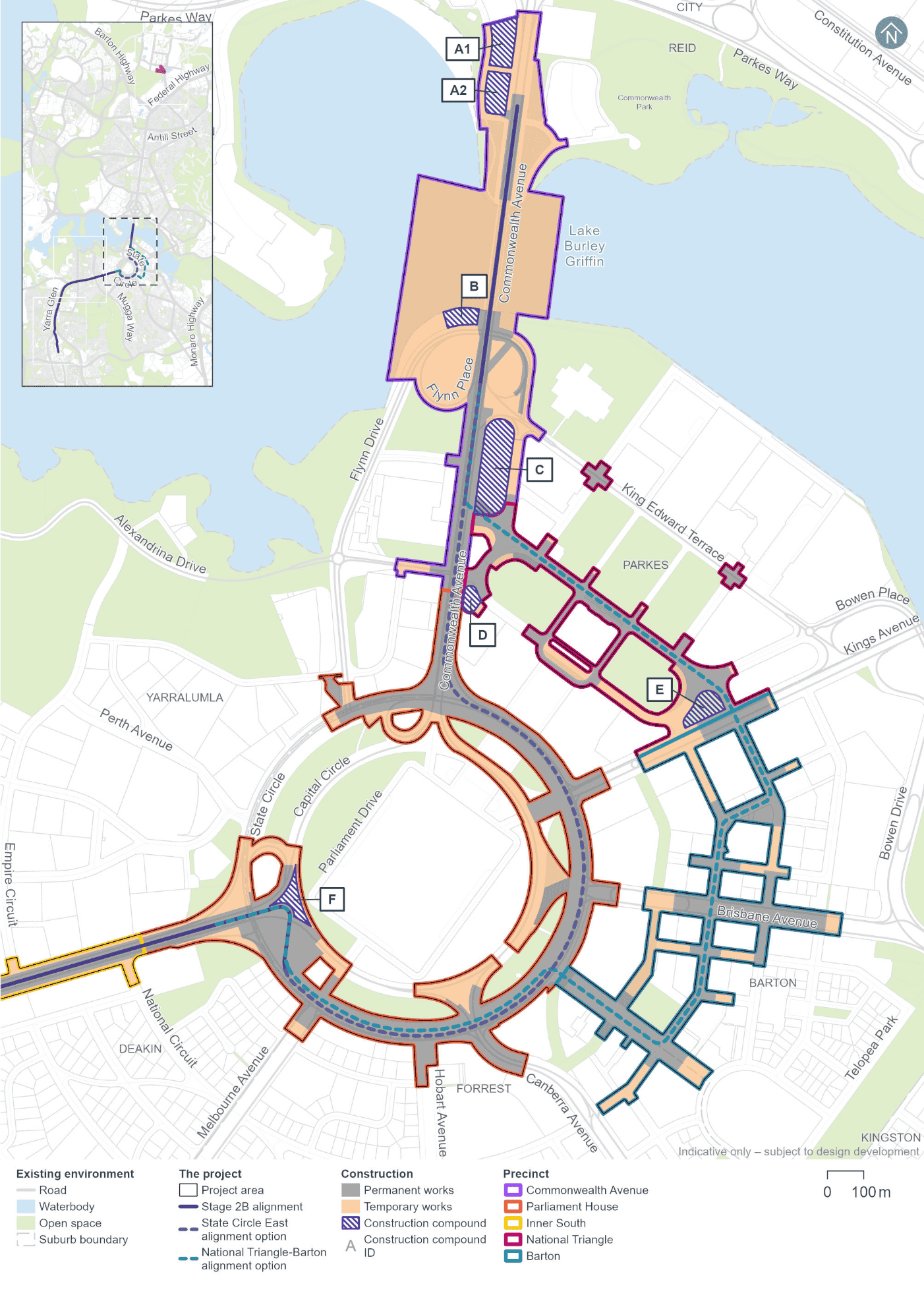
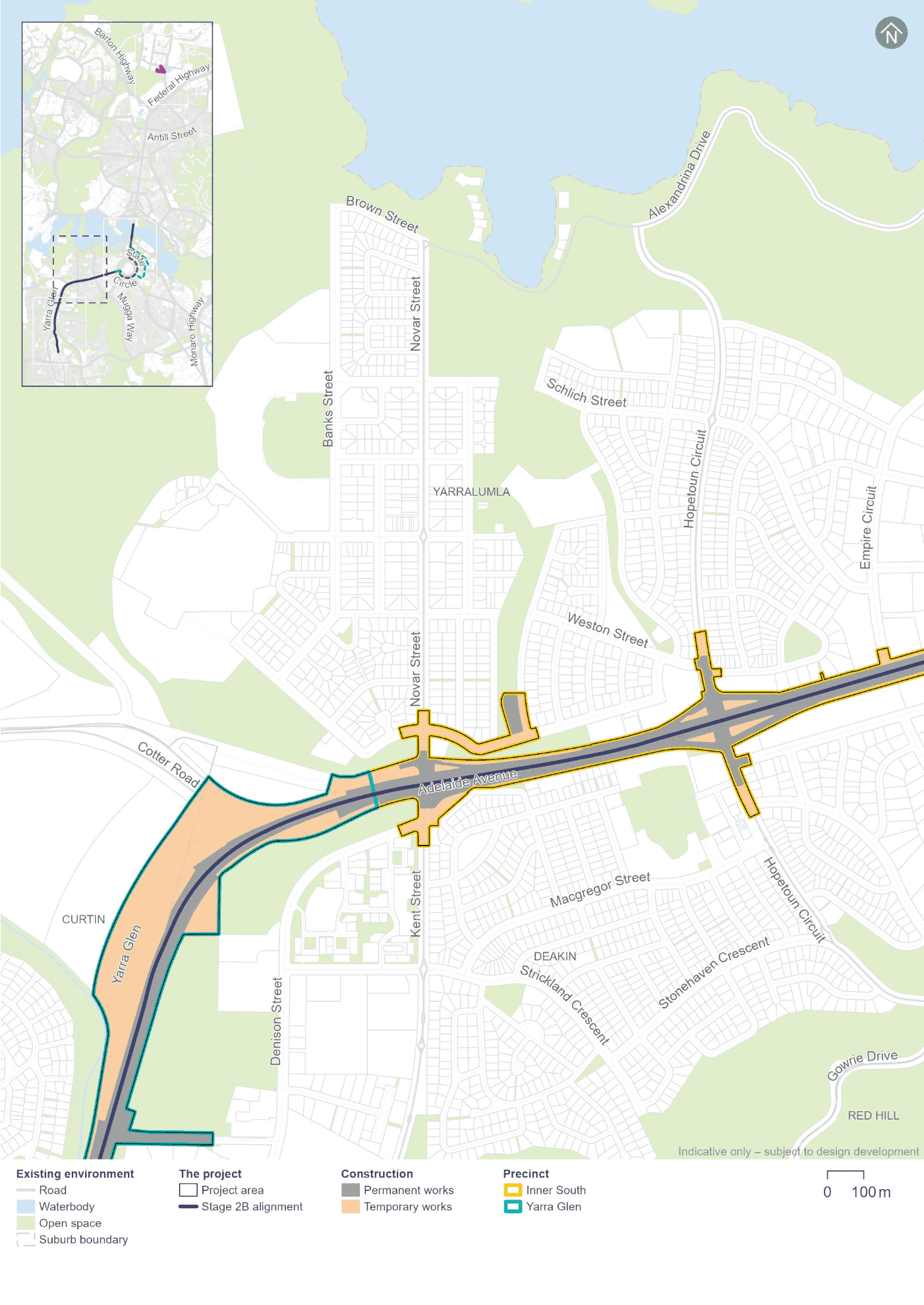
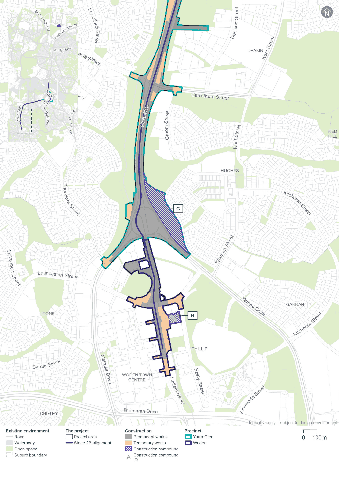
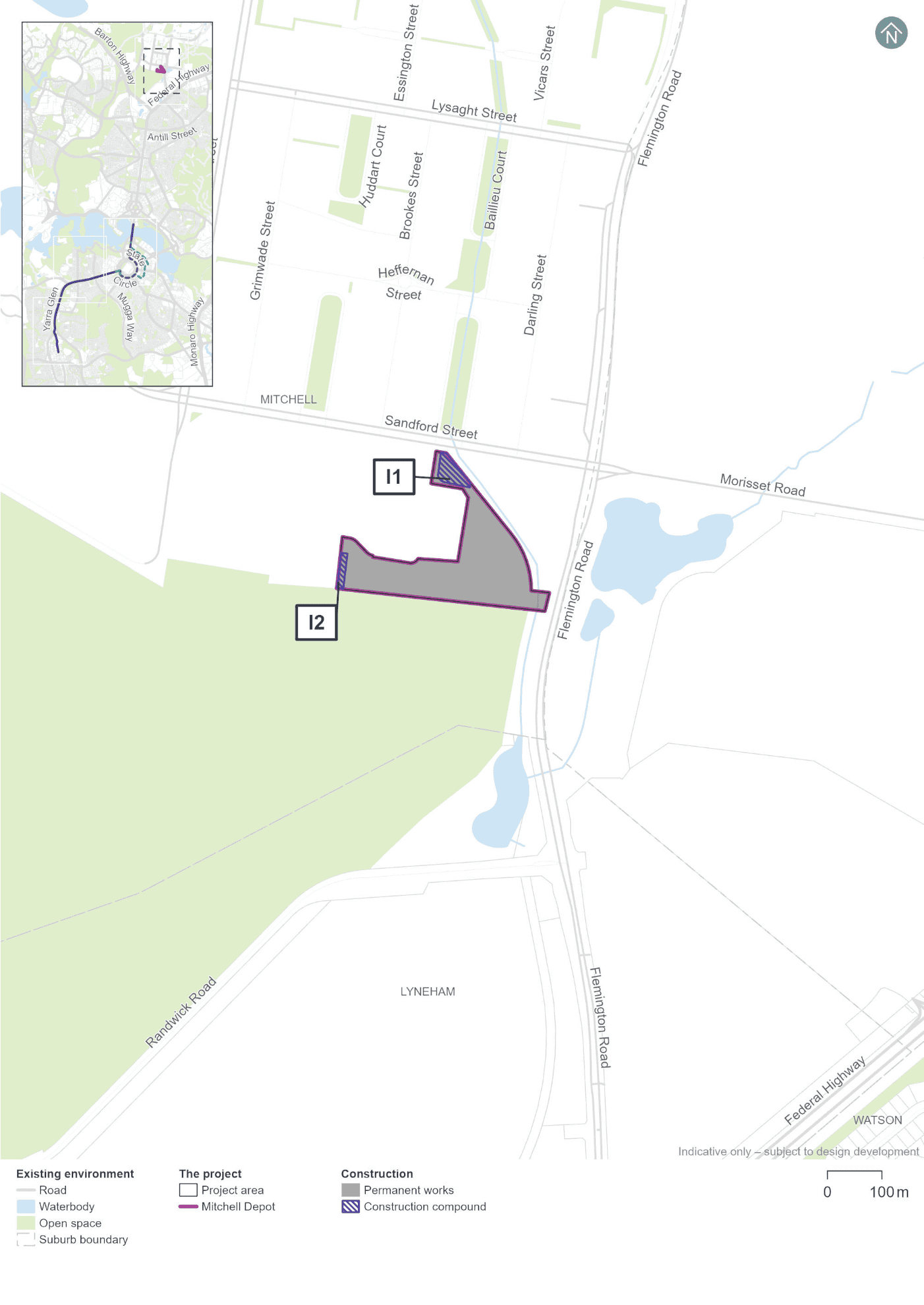
Construction activities associated with the Project would occur within the 'Project area', as shown on Figure 6-1 to Figure 6-4. The Project area would allow sufficient area for both permanent and temporary works required to deliver the Project. Temporary occupation of land would be subject to a licence or lease over the land, where required. Permanent works would include new and altered infrastructure to support operation of the Light Rail extension to Woden, such as the track, stop infrastructure, bridges, landscaping, and traction power substations (TPSs). Permanent Project elements are described in Chapter 5 (Project description).
Temporary works would include areas for short-term storage of construction plant and equipment, construction compound areas, traffic management, and temporary alterations required to deliver the permanent Project elements. Land required for temporary works would be used at different times depending on the stage of construction, and construction requirements at a particular location. Temporary works would vary over time during the construction period, and would proceed along the Project alignment. Construction planning would aim to minimise and manage potential construction phase environmental impacts through careful selection of locations and scheduling of temporary works across the Project area. The extent and location of temporary works would depend on which alignment option is selected for the Project.
Indicative construction compound locations are shown in Figure 6-1 to Figure 6-4 and described further in Section 6.6.1. All indicative construction compound locations would be required regardless of which alignment option is selected. Some temporary work areas may also be required in each precinct for each alignment option. For example, temporary work areas along Sydney Avenue in the Barton precinct may be used to facilitate construction of the State Circle East alignment option.
Further information about the Project's land requirements, and the potential property impacts of these requirements is provided in the property and land use assessments in Section 11.8.
6.1.1 Program
Design and approvals
Design development and construction planning for the Project is ongoing and would continue up until anticipated commencement of construction.
Subject to statutory requirements and the timing of decisions to be made by environmental and planning regulatory agencies with respect to the Project and this EIS, it is anticipated that necessary environmental approvals associated with this EIS would be secured in 2026.
Construction and early and enabling works
Subject to approvals and the Project's procurement strategy, major construction work is anticipated to commence in 2029 and would take about four to five years to complete. The construction duration would depend on further design development, investigations (including geotechnical and utilities), and detailed construction planning, including the construction contractor's final delivery methodology. Early and enabling works may be required prior to 2029, subject to detailed design and construction planning. A decision on how the construction works would be packaged would be made as part of ongoing planning for Project delivery.
Construction is anticipated to occur concurrently across each precinct from 2029.
The construction of Light Rail Stage 2A (LRS2A) is anticipated to be completed in 2027 followed by a period of testing and commissioning, and would begin operation prior to the main construction works of the Project.
Testing, commissioning and operation
The testing and commissioning phase would begin towards the end of completion of the main construction works and would take around 12 months. The first passenger services are proposed to start in 2034.
Design life and potential decommissioning
The design life (the period of time over which the Project is designed to meet specified requirements) of Project elements varies depending on their nature. For example bridges, the covered section, and retaining walls have a design life of 100 years. Other elements such as light rail stop structures, trackform structures, drainage structures, and pedestrian footpaths have a lower design life ranging between 75 and 40 years. As the Project elements approach those timeframes, their operational performance would be reviewed and decisions made at that time regarding further investment in prolonging the life of the infrastructure or whether decommissioning and replacement of elements would be required.
6.2 Early and enabling works
Early and enabling works would be carried out before the start of major construction work. These works would reduce the duration of the major civil construction works and associated disruptions to traffic and surrounding sensitive land uses. The scope of early and enabling works would be subject to the delivery strategy and a specific CEMP (refer to Section 2.2 of Appendix L (Environmental Management Plan outline). Early and enabling works may include:
- Surveys and investigations, such as land surveys, geotechnical investigations, utility investigations, bridge foundation assessments, archaeological surveys, property condition surveys, soil sampling and monitoring work
- Installing site environment management controls, including site fencing, environment protection zones, sediment and erosion controls and screening
- Relocating bus stops and diversions of bus routes
- Removing redundant structures (as required)
- Temporary fencing of works areas
- Establishing construction compounds, ancillary facilities and work areas for early and enabling works, including but not limited to providing access, erecting demountable buildings, and solid hoarding or temporary fencing. Construction compound locations are shown in Figure 6-1 to Figure 6-4 and described further in Section 6.6.1
- Supplying power, water, and other utilities to construction compounds, ancillary facilities, and work areas
- Vegetation removal, trimming, mulching, and tree removal/relocation where required
- Establishing temporary roads and access tracks, drainage measures, pedestrian, and cyclist diversions
- Preparing work areas for main construction works, including property adjustments (such as temporary driveways and access points)
- Relocation, protection and the potential replacement or removal of utilities
- Any other work that may be required to support the commencement of major construction works.
Temporary connection to the water, telecommunications, and power supply networks may also be required during establishment of compounds and ancillary facilities. Engagement with relevant utility providers would be carried out with respect to timing and location of temporary connections to ensure sufficient capacity is available. Connections to existing power supply networks would be prioritised where feasible.
6.3 Main construction works
Main construction works would include elements directly related to light rail (refer to Section 6.3.1 and 6.3.6) as well as civil works required to install light rail infrastructure such as bridges (Section 6.3.4) and the covered section (Section 6.3.5). Main construction works may also include ancillary activities such as establishing active travel links (Section 6.3.7) and roadworks (Section 6.3.8).
6.3.1 Light rail infrastructure
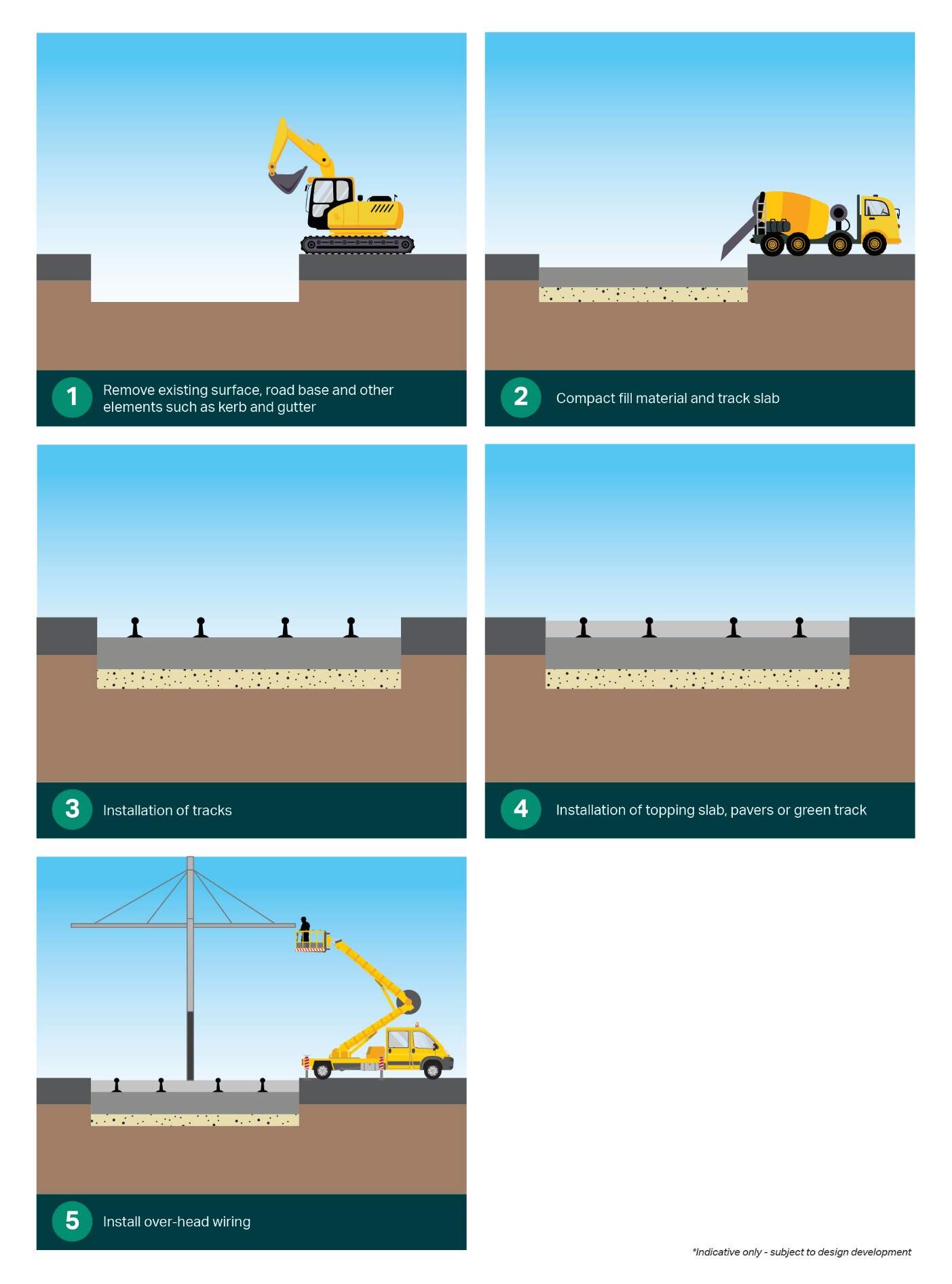
Light rail infrastructure would include trackform, stops, over-head wiring, street lighting, signalling, drainage and services. The construction of the light rail infrastructure would include:
- Civil works (including excavation and earthworks, installation of track drainage, the combined services route, and concrete). This would form the base of the trackform
- Track installation (including installation of reinforcing steel, installation of electrical stray current and bonding elements, and welding of the track)
- Installation of over-head wiring and poles
- Installation of street lighting, closed circuit television (CCTV), communications and signalling equipment.
Works typically required to construct the light rail infrastructure are described in the following sections.
Civil works
Civil works required to install light rail infrastructure are expected to involve:
- Removing existing surface infrastructure (such as roads, medians, and asphalt), and other elements such as kerb and gutter
- Earthworks (refer to Section 6.3.2), including subgrade works for the track slab foundation and compaction of fill material, construction of retaining walls (refer to Section 6.3.8) and backfilling areas of excavation
- Installing service conduits
- Relocation, protection and the potential replacement or removal of utilities
- Constructing stormwater drainage
- Concrete work, including placing steel reinforcement and concrete formwork and pouring concrete in-situ or installing pre-cast concrete slabs
- Installing pavement for track slab and kerbs for the turnback facilities at the light rail terminus at the Woden Interchange
- Reinstating affected areas including roads, paths, and grassed areas
- Public domain works (refer to Section 5.2).
Track installation
Track installation is expected to involve:
- Installing track into concrete formwork (for embedded and green track options), including track laying, welding, and grinding
- Installing concrete sleepers, track, and infilling ballast or permeable gravel between tracks (if required, subject to detailed design development)
- Installing rail crossovers at Sydney Avenue Stop and Hopetoun Circuit Stop for emergency access use
- Installing the end of line infrastructure including turnback facilities at Woden Interchange
- Installing embedded and cast-in rail systems infrastructure, such as conduits, cabling, and pole foundations
- Surface finishing, depending on the trackform to be applied at each location (refer to Section 5.3.1)
- Installing irrigation and turfing for green track (if required)
- Reinstating affected areas
- Line marking on roads.
Figure 6-5 shows a simplified and indicative construction process for installation of the light rail tracks.
Over-head wiring and poles
As discussed in Chapter 5 (Project description), the Project would transition between wire-free running and over-head power supply at the Hopetoun Circuit Stop. Installation of over-head wiring and poles (from Hopetoun Circuit Stop to Woden Interchange) is expected to involve:
- Removing existing pavement and excavating footings
- Placing prefabricated reinforcement cage, base plate, and other sub-structure elements
- Concrete pouring
- Erecting poles
- Stringing of over-head wires, utility connection, installing droppers, and wiring terminations.
Street lighting, CCTV and signalling
Installation of street lighting, CCTV and signalling is expected to involve:
- Installing underground conduits and access pits from the points of supply for both communications and electrical power to each of the traffic signal posts and associated electrical cabinets
- Constructing pole footings
- Erecting the signal and streetlight posts
- Installing cabling
- Connecting and commissioning the traffic lights (and integrating them with the light rail signals system where required).
For the National Triangle-Barton alignment option, some adjustments to traffic signals would be required on King Edward Terrace at its intersection with Parkes Place East and Parkes Place West. These areas are shown on Figure 6-1.
6.3.2 Earthworks
Earthworks would be required to construct light rail infrastructure, bridges, traction power substations (TPSs), to undertake road and utility works, and to remove existing concrete in some locations. Fill material would be required for sub-grade works and retaining wall construction, and to backfill excavations.
The management of excavated materials would be as per the following hierarchy:
- Reuse material that has appropriate engineering properties and meets soil quality standards within the Project area, where possible
- Reuse or recycle surplus usable material on other projects within or nearby the ACT
- Transport excess material, including any contaminated material, that cannot be reused within the Project area or other projects, off-site for treatment and/or disposal at a licensed facility as determined by its waste classification.
Management of contaminated materials would be as outlined in Section 11.6.
The estimated quantities of materials associated with earthworks cut and fill are provided in Table 6-1. Where fill material is not available from earthworks, suitable material would be sourced from other projects, where possible, to divert waste from landfill.
Further information on waste management is provided in Section 11.12.
| Precinct | Volumes of spoil (m3) | |||||
|---|---|---|---|---|---|---|
| State Circle East alignment option | National Triangle-Barton alignment option | |||||
| Fill material | Excavated material | Excess spoil | Fill material | Excavated material | Excess spoil | |
|
Commonwealth Avenue |
500 |
20,000 |
19,500 |
500 |
15,000 |
14,500 |
|
Parliament House |
10,000 |
84,000 |
74,000 |
3,000 |
43,000 |
40,000 |
|
Inner South |
10,000 |
36,000 |
26,000 |
10,000 |
36,000 |
26,000 |
|
Yarra Glen |
38,000 |
55,000 |
17,000 |
38,000 |
55,000 |
17,000 |
|
Woden |
5,000 |
11,000 |
6,000 |
5,000 |
11,000 |
6,000 |
|
National Triangle |
2,000 |
20,000 |
18,000 |
|||
|
Barton |
2,000 |
31,000 |
29,000 |
|||
|
Mitchell Depot |
21,000 |
21,000 |
21,000 |
21,000 |
||
|
Total |
63,500 |
227,000 |
163,500 |
60,500 |
232,000 |
171,500 |
6.3.3 Road works
Road works would be required for the Project to deliver the road network changes described in Section 5.9. This would include construction of new kerbing, drainage, asphalt and concrete pavements, installation of associated road furniture, such as barriers, and installation of signage and pavement markings.
Construction of roads would involve:
- Demolishing existing kerbs and pavements
- Ground excavation to required formation levels
- Installation of road, pavement, and subsoil drainage
- Preparing the ground sub-grade
- Installing and compacting road base material
- Constructing kerbs and gutters
- Placing asphalt (or concrete)
- Installing road furniture
- Line marking and placing pavement markers.
The State Circle East alignment option would require realignment of the road carriageway on the inside edge of State Circle, into Capital Hill, as described in Section 5.9.
Works would generally involve relocation of utilities; reconstruction of drainage; and reconstruction of the inner verge including retaining walls. Widening of the existing median would be carried out (for the State Circle East alignment option only). Following these works, excavation for light rail stops and trackform; intersection reconfiguration and construction; and trackform and stop construction would be carried out.
6.3.4 Bridges
Construction of new bridges, and modification, removal, or protection of existing bridge structures would include (refer further to Section 5.5):
- Construction of new light rail bridges (four land based structures and one structure over Lake Burley Griffin)
- Construction of four new pedestrian and cyclist bridges
- Removal of the existing Melrose Drive road bridge over Yarralumla Creek between Yamba Drive and Melrose Drive and construction of a new light rail bridge over Yarralumla Creek
- Removal of one existing pedestrian bridge across Yarralumla Creek north of Phillip Oval.
Typical land bridge construction
The land bridges (light rail and pedestrian) are expected to be constructed in the following sequence:
- Ground preparations including installation of ground retaining structures (if required)
- Construction of the bridge substructure including piles, pile caps, and footings
- Construction of the bridge superstructure including bridge piers, abutments, headstocks, bridge beams/ girders, bridge deck, wing walls, and approach slabs
- Installation of the bridge barriers
- Construction of the trackform and rails (for light rail bridges) (refer to Section 6.3.1)
- Installation of the bridge finishings including handrails and lighting.
Light rail bridge over Lake Burley Griffin
Construction of the light rail bridge over Lake Burley Griffin would occur between the existing Commonwealth Avenue road bridges. Lake Burley Griffin is an important landscape feature and is an environmentally sensitive area. As such, the construction methodology adopted would reflect best practice, considering relevant environmental sensitivities and recreational users of the lake and its foreshore areas. Appropriate approvals and licences would be secured prior to commencement of construction. Chapter 21 (Environmental management and mitigation measures) includes commitments to specific and detailed measures to manage hydrology and water quality during construction works within Lake Burley Griffin that would be included in a Surface Water and Groundwater sub-plan(s) for the Project. There will be ongoing consultation with key stakeholders including the NCA in developing the methodology for construction of the light rail bridge over Lake Burley Griffin.
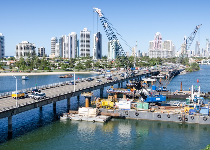
Temporary structures would be required within Lake Burley Griffin to allow access to the bridge construction area. A service jetty would be installed on the southern side of Lake Burley Griffin, to the west of Commonwealth Avenue to service two barges (a boat that transports heavy goods - refer to Figure 6-6 for an example of a barge). Cranes would be secured on the barges to transport materials to and from the barge.
Piling works would use the barges and would include driving or vibrating either pre-cast concrete piles, or steel casings into the rock bed of Lake Burley Griffin. Once installed, the steel casings would be augured and cleaned out, a reinforcing cage would be installed, and concrete would be poured to the required height. Temporary piers may also be required, depending on the selected bridge construction methodology (refer to Table 6-2). The temporary piers would likely be constructed using steel casings to allow removal of the temporary piers once bridge construction is complete.
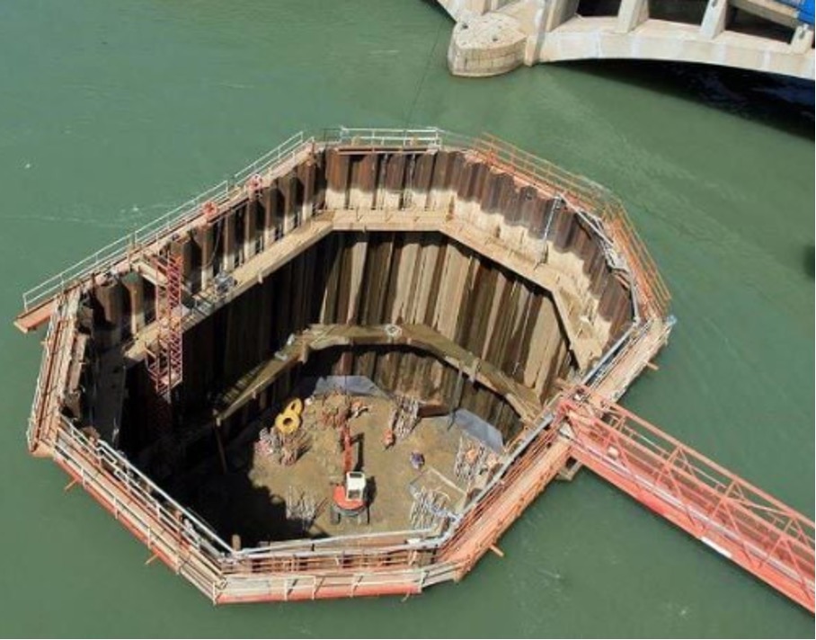
Cofferdams1 would be required around each pier to allow safe and dry access to the bridge construction area. An example of a cofferdam structure is shown on Figure 6-7. The cofferdams would be constructed by installing temporary piles, pumping water out, and installing access platforms. Piling works would then be undertaken, involving driving or vibrating steel casings or interlocking sheet piles, as per the methodology outlined above.
1 Watertight enclosures from which water is pumped to expose the bed of a body of water to permit the construction of a pier. Source: Britannica, 2023 https://www.britannica.com/technology/cofferdam
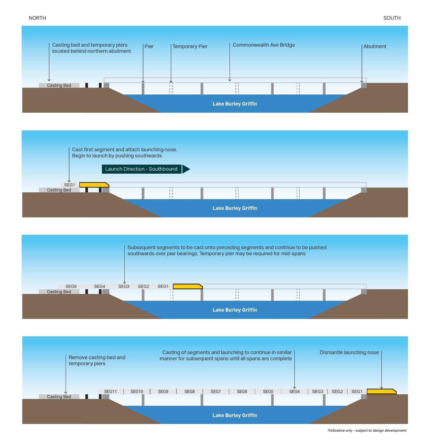
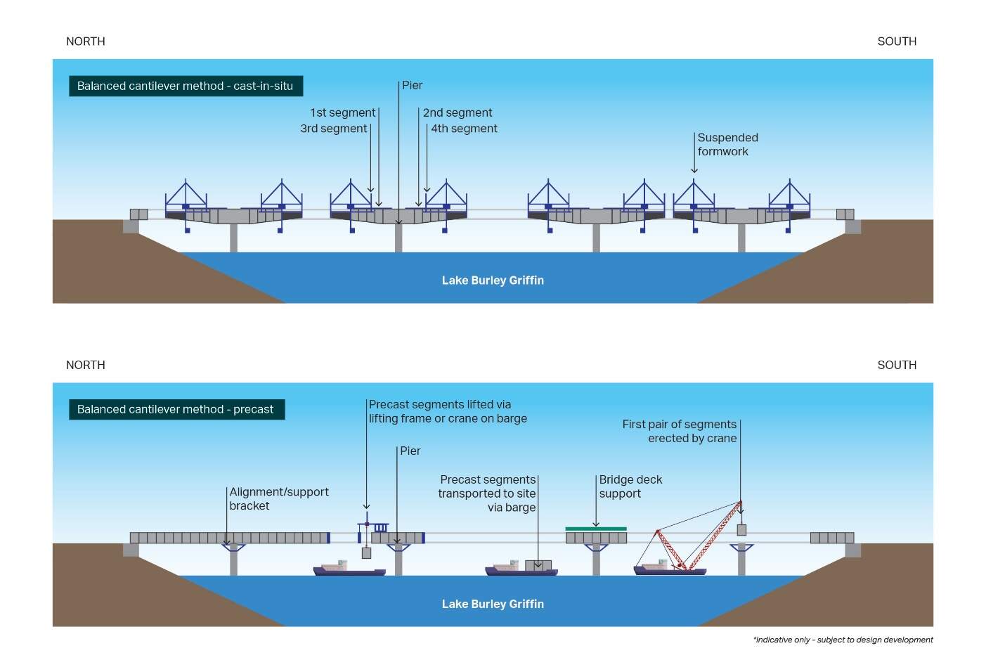
After the piling, coffer dam installations and pier works are completed, the bridge structure would be built, using either the incremental launch method or the balanced cantilever method. The two methods are described and shown in Figure 6-8 and Figure 6-9.
Bridge construction is highly specialised and is likely to be undertaken using one of these two methodologies. Factors to be considered in any decision on a preferred bridge construction method would include construction program and related efficiencies including cast-in-situ or pre-cast concrete construction requirements, construction footprint (including access for recreational lake users) and environmental impact avoidance/ management. The selected construction methodology would be subject to ongoing design development and detailed construction planning in consultation with relevant stakeholders.
| Bridge construction method | Description of method |
|---|---|
|
Incremental launch method (refer to Figure 6-8) |
The incremental launch method would involve staged construction of the bridge deck between each abutment, including:
An excavation area would be required within the Commonwealth Avenue median to allow space for launching the bridge construction, and for on-site casting of each bridge segment. A temporary retaining structure (e.g.sheet piles) would also be required along both sides of the Commonwealth Avenue median |
|
Balanced cantilever method (refer to Figure 6-9) |
The balanced cantilever method would involve progressively joining bridge segments from each pier. This method could be undertaken using the cast-in-situ, or precast concrete options, as described below:
|
6.3.5 Covered section between Commonwealth Avenue and State Circle (State Circle East option only)
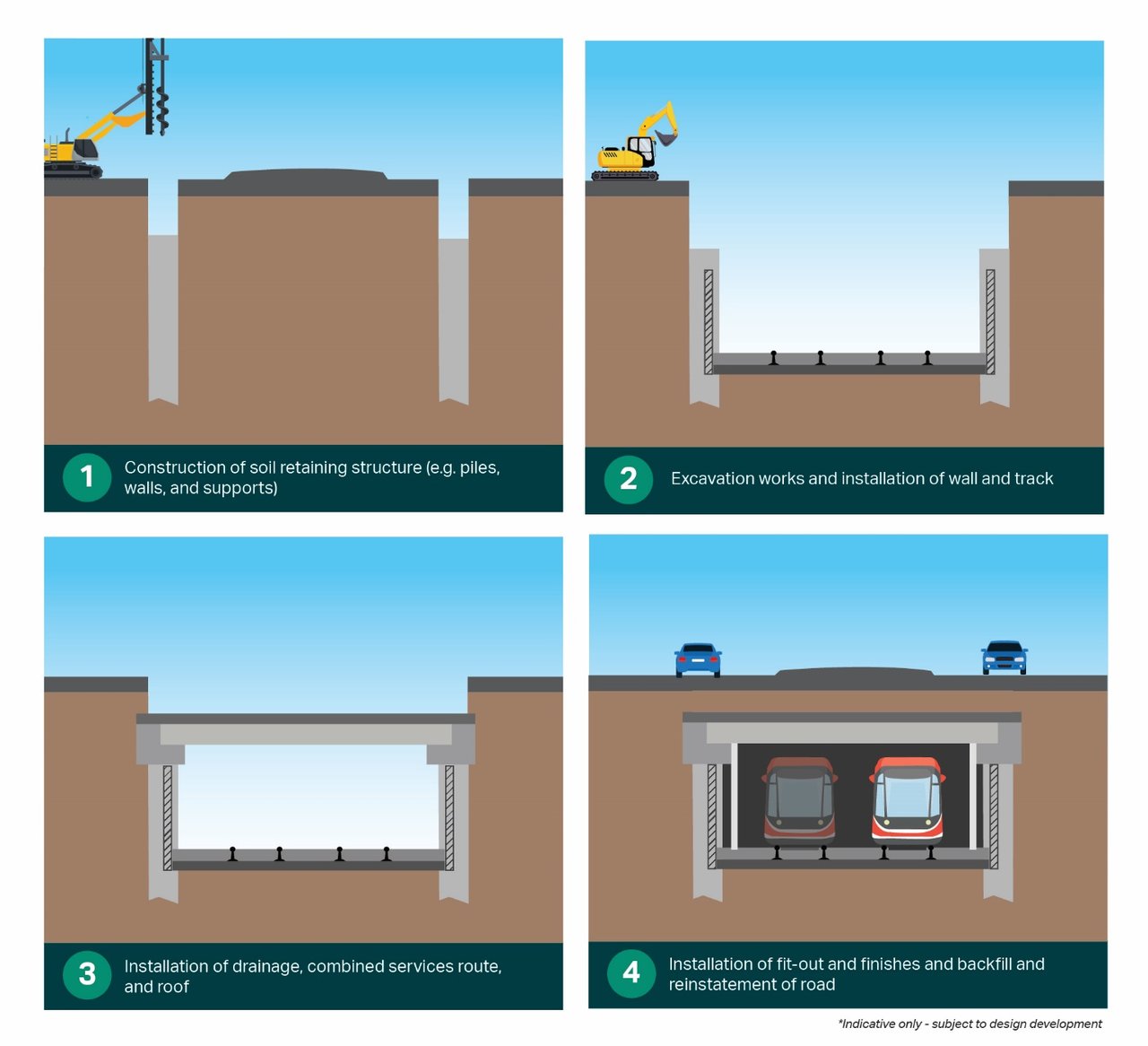
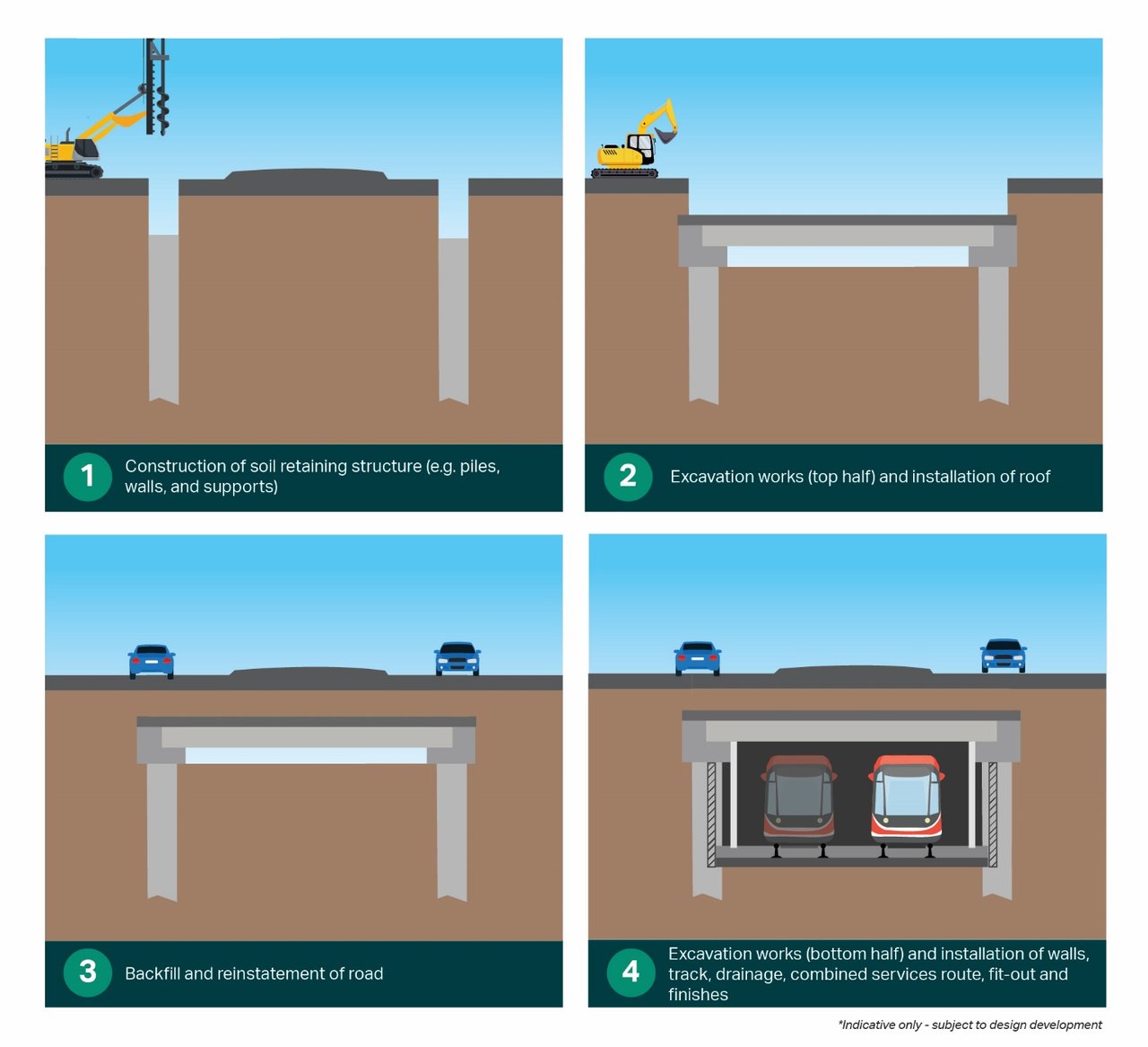
For the State Circle East alignment option, the light rail alignment would travel along the Commonwealth Avenue median and transition under the southbound carriageway through a covered section towards State Circle. A 'cut and cover' construction method is proposed for construction of this covered section, which could involve one of two construction methods: bottom-up; or top-down. Both methods are described further in Table 6-3 and shown in Figure 6-10 and Figure 6-11. The selection of a construction method would be subject to ongoing design development and detailed construction planning, with consideration given to ground conditions and traffic management.
| Construction method type | Description of method |
|---|---|
|
Bottom-up construction method |
The following stages would apply in the bottom-up construction method for the covered section:
The bottom-up construction method would be used if ground conditions are found to be less stable during detailed design and construction planning. For this option, reopening State Circle to traffic would only be possible once construction of the covered section is complete. |
|
Top-down construction method |
The following stages would apply in the top-down construction method for the covered section:
The top-down construction method would be used if ground conditions are found to be more stable during detailed design and construction planning. For this option, reopening State Circle to traffic would be possible once the roof of the covered section is installed and backfilled. |
6.3.6 Stops
Construction of each light rail stop would involve:
- Ground preparations including demolition of existing pavements within the stop footprint
- Excavation and earthworks
- Installation of stormwater drainage
- Construction of the stop platforms including installation of footings and ramps
- Installation of the roof and canopy structure
- Installation of systems equipment
- Installation of lifts, and stairs as required
- Construction of cyclist parking facilities and driver facilities if required
- Installation of stop services and systems including electrical and lighting, communications, closed circuit television (CCTV), and water
- Installation of the stop furniture such as seats, bins, bollards, handrails, signage (e.g. wayfinding signage), and pavement markings.
6.3.7 Active travel links
Where existing active travel (walking, cycling, and micromobility) networks are affected by construction works, the active travel links would be reinstated or reconfigured to integrate into the wider active travel network. For the new pedestrian and cyclist bridge structures to be provided as part of the Project, active travel links would be constructed as part of the bridge deck structure. In other areas, the active travel links would be constructed as part of other Project elements, such as modified roads or areas adjacent to modified roads and stops.
Generally, where excavation for the active travel links is required, it would be completed as part of the overall Project earthworks (refer to Section 6.3.2). This would typically be followed by:
- Installing formwork
- Pouring concrete
- Installing drainage and services (as required)
- Finishing the surface (including painting and line marking)
- Installing wayfinding and customer information signage (as required).
In addition, construction of sections of elevated structures would be required for the shared path to be provided on the eastern side of Yarralumla Creek in Woden (refer further to Section 5.8). Works to construct this shared path would include:
- Ground preparations including installation of ground retaining structures (if required)
- Piling works, including construction of pile caps, and footings
- Construction of the elevated structure including piers and abutments
- Installation of safety barriers
- Installation of finishings including handrails and lighting.
The approach to construction of active travel bridges is detailed in Section 6.3.4.
6.3.8 Other infrastructure
Adjustments to the existing Mitchell Depot
As described in Section 5.10.7, adjustments to the existing Mitchell Depot would be required to meet the Project's operational needs. This would include support for up to an additional 12 light rail vehicles (LRVs) for the Project.
Construction work at the Mitchell Depot would involve:
- Earthworks and constructing soil retaining structures
- Installing new drainage and services including a combined services route, and over-head wiring and poles
- Installing new stabling track, turnouts and buffer stops
- Constructing facilities to support stabling and maintenance activities including storage facilities, a workshop, office space and carpark
- Installing new signage and linemarking
- Installing light rail systems and operational infrastructure.
Traction power substations (TPSs)
Construction of TPSs would involve:
- Installing underground services and pits
- Constructing foundations, footings, and base slabs
- Constructing and/ or delivery and installation of substation structures and electrical equipment, including wiring fit-out
- Installing earthing and lighting systems
- Installing high voltage cables between substations and light rail stops, and to the existing electricity supply network
- Installing the substation units
- Installing access paths and service parking bays as required
- Ground finishing with concrete, pavers, or other materials
- Installing the façade.
Retaining walls
Retaining walls would vary in structure and construction methodology, depending on location. Construction activities are expected to involve:
- Excavating below the existing ground surface to prepare the foundation for the retaining wall
- Installing reinforcing steel and formwork, and concrete pouring (for cast in-situ bases and walls)
- Installing precast segments and retaining straps (for reinforced earth walls)
- Installing subsurface drainage systems, including free draining aggregate and geotextile materials
- Progressive backfilling and compaction
- Installing any surface drainage at the top or bottom of the retaining wall
- Installing retaining wall finishes.
Stormwater drainage
Stormwater drainage systems (including subsoil drainage) would include installation of drainage pipes, gullies and pits, culverts, manholes, and chambers.
Drainage installation would involve one of two construction methods depending on the location. One method would involve micro-tunnelling, a trenchless method that would install the drainage system without excavating the surface. The second method would involve trenching, and would include:
- Excavation
- Placing bedding material
- Installing pipes/ pits
- Backfilling
- Compacting the trenches.
Utilities
Existing utilities within the Project area which may be affected to various degrees by the Project. In consultation with the relevant utility provider, each utility may be subject to:
- Temporary protection during construction
- Permanent protection
- Relocation
- Provision of spare conduits or sleeving.
The Project would also include new utilities, such as electricity supply to LRVs and lighting, as well as light rail systems such as power and communications.
The protection, decommissioning and/ or removal of utilities would be completed early in the Project construction period but may also be staged during the main works depending on construction planning requirements.
6.4 Finishing, testing, and commissioning
6.4.1 Finishing works
Construction related equipment and infrastructure would be removed at the end of construction work in each work area. Finishing works would be completed progressively (as far as practicable) and would generally include:
- Demobilising construction compounds and works areas, removing all equipment, and temporary infrastructure
- Removing materials, waste, and redundant structures from the Project area
- Removing temporary fencing
- Rehabilitating disturbed areas
- Landscaping, including tree replacement
- Erecting signage, and roadside furniture such as street lighting
- Rectifying defects.
6.4.2 Testing and commissioning
Testing and commissioning would involve trial running of light rail infrastructure, including LRV movement, driver familiarisation, and integration of new and existing power, communications and signalling systems.
Testing and commissioning of stops would include lighting, help points, passenger information displays, ticket vending machines and validation scanners, CCTV, public address systems, precise clock, and audio frequency induction loops.
6.5 Construction working hours
Standard construction hours would be Monday to Saturday, 7am to 6pm. Where possible works would be conducted during standard construction hours. However, as the Project would be carried out predominantly within live road corridors, some construction works would be required outside of standard construction hours to:
- Minimise disruptions to traffic
- Minimise disturbance to surrounding landowners and businesses
- Maintain safe and efficient operation of key roads and public transport facilities.
Works that would be required outside of standard construction hours may include:
- Delivery of oversized plant, equipment, and structures that the police or other authorities determine require special arrangements to transport along public roads
- Constructing track infrastructure and undertaking road works at busy intersections or where temporary road closures are required during periods of lower traffic volumes
- Installation of large elements such as bridge beams/girders
- Certain utility adjustments depending on the location and requirements of the utility provider, particularly where disruption to essential services, required system conditions (such as low-flow conditions for sewers), and/ or worker safety considerations do not allow work during standard construction hours
- Road closures and traffic switches during night works, to be reopened the following day.
High noise and vibration intensive works would be limited to standard construction hours as far as practicable. Mitigation measures identified in Chapter 21 (Environmental management and mitigation measures) would be implemented to manage potential noise and vibration impacts during works outside standard construction hours.
6.6 Construction resources and ancillary facilities
6.6.1 Construction compounds and ancillary facilities
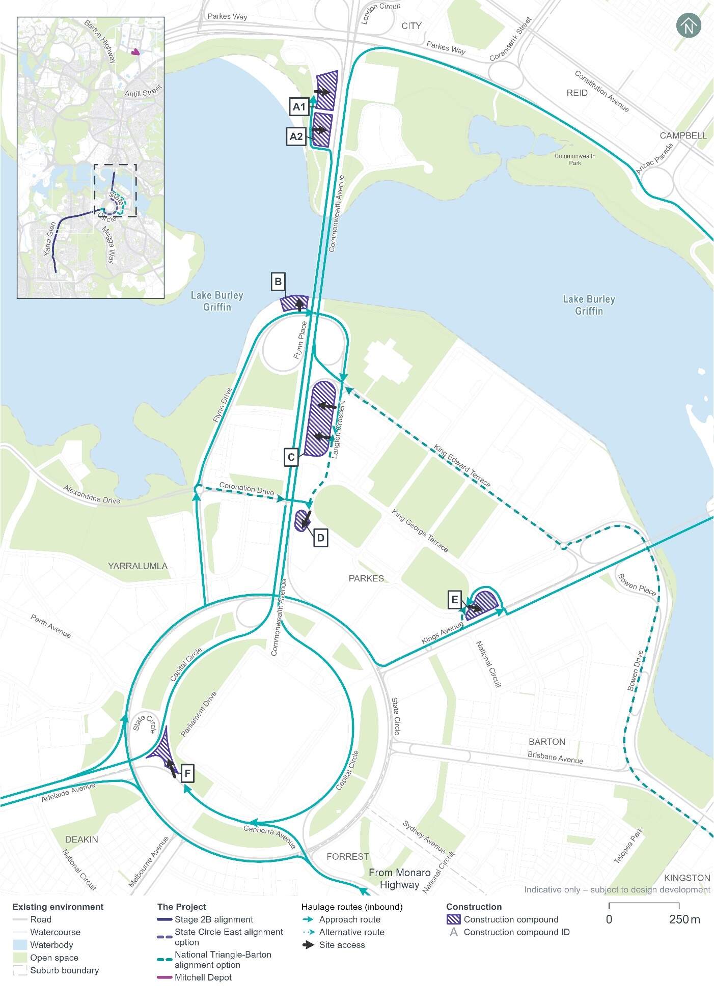
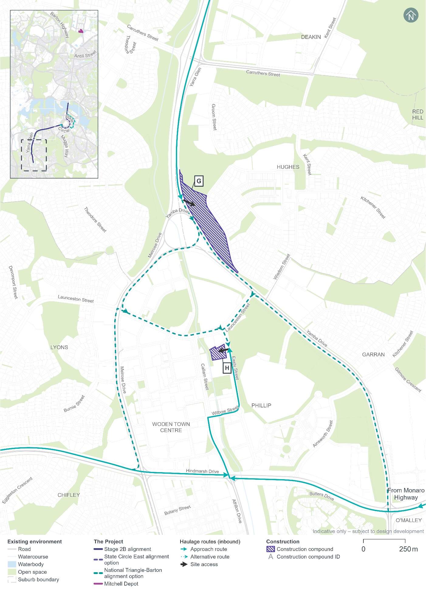
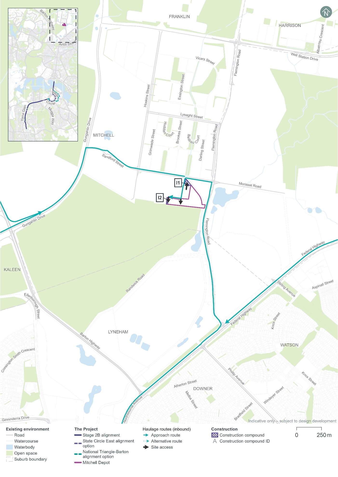
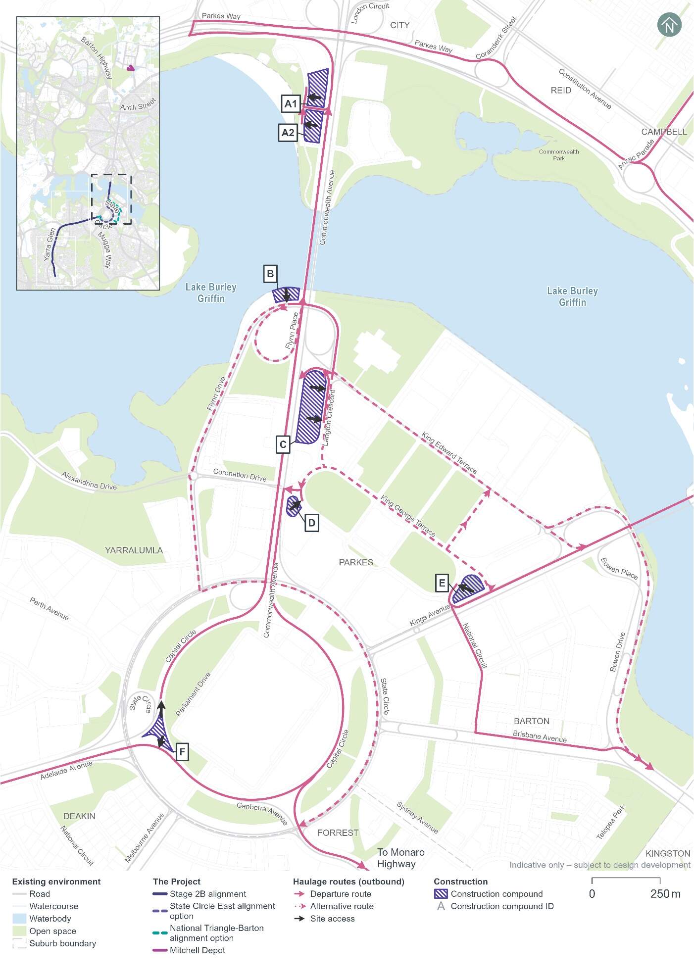
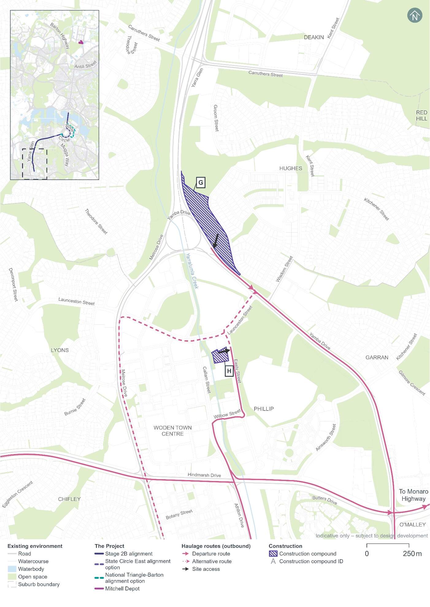
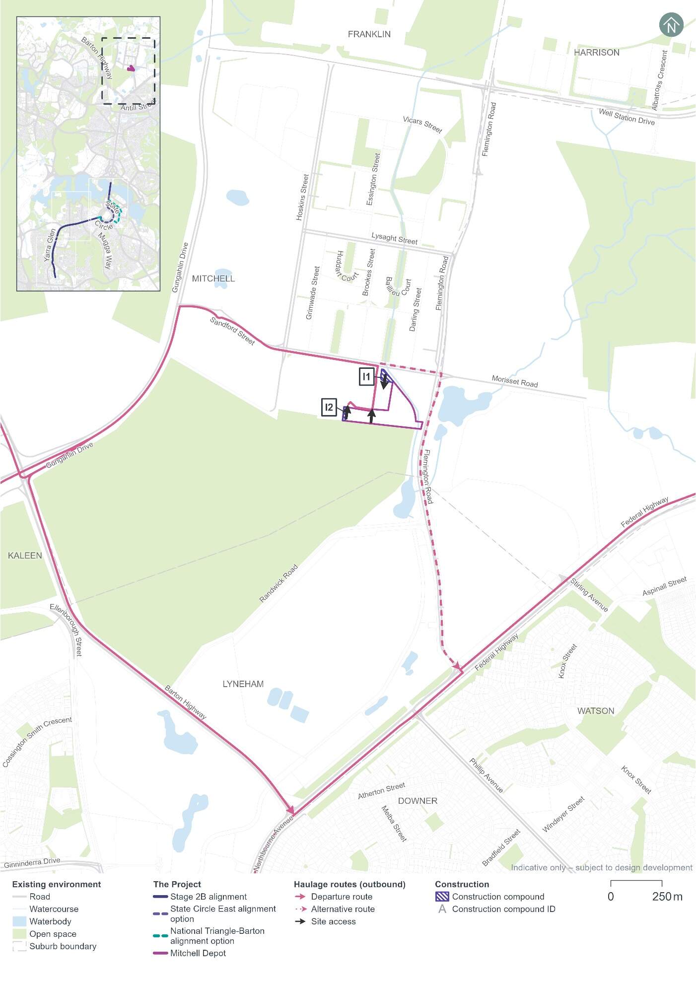
Construction compounds would be required to support and service construction activities and would likely be required for the duration of the construction program. Information on the land custodianship and relevant land use policy applying to land affected by construction compounds is included in Appendix H (Consultation). Indicative construction compound locations are shown in Figure 6-1 to Figure 6-4 and summarised in Table 6-4.
Construction compounds would support staff and worker accommodation (such as temporary office buildings and amenities) and storage of plant, equipment, and construction materials. Solid hoarding or temporary fencing would be installed around each of the construction compounds. Following construction works, land occupied by the construction compounds would be rehabilitated.
| Precinct/site | Compound | Location | Block details |
|---|---|---|---|
|
Commonwealth Avenue |
A1 |
Acton Waterfront car park at Corkhill Street (consistent with the compound location used for LRS2A) |
Block: 24 Section: 33 Division: Acton |
|
A2 |
Acton Waterfront car park at Albert Street (consistent with the compound location used for LRS2A) |
Block: 1 Section: 95 Division: Acton |
|
|
B |
Yarralumla Parkland, Commonwealth Avenue south-west cloverleaf on the southern side of Lake Burley Griffin and adjacent to the existing bridges |
Block: 12 Section: 42 Division: Yarralumla |
|
|
C |
Langton car park opposite Treasury building, Parkes |
Block: 1 Section: 25 Division: Parkes |
|
|
National Triangle |
D |
21 Queen Victoria Terrace Parking |
Block: 3 and 4 Section: 23 Division: Parkes |
|
E |
King George Terrace and Kings Avenue |
Block: 1 Section: 22 Division: Parkes |
|
|
Parliament House |
F |
Capital Hill West |
Between Adelaide Avenue and Capital Circle |
|
Yarra Glen |
G |
Parkland east of Yarra Glen/Yamba Drive roundabout, Hughes |
Block: 5, 6, and 9 Section: 28 Division: Hughes |
|
Woden |
H |
Easty Street car park in Woden |
Block: 30 and 31 Section: 80 Division: Phillip |
|
Mitchell Depot |
I1 |
Sandford Street |
Block: 2 Section: 16 Division: Mitchell |
|
I2 |
Within the existing Mitchell Depot site |
Block: 3 Section: 16 Division: Mitchell |
As part of the early and enabling works (refer to Section 6.2), construction compounds would require connections to utilities such as electricity, telecommunications, water and sewer. Construction compounds would include:
- Offices and meeting rooms
- Amenities and ablution blocks
- All-weather protected cribbing areas
- Access ramps, stairs, and outdoor decking areas
- Worker crib sheds
- Parking and storage of plant, equipment, and vehicles
- Storage of construction materials
- Storage of bulk materials and stockpiles
- Storage containers
- Separated waste skips.
In addition to the construction compounds, smaller short term 'satellite' ancillary facilities would also be required. These ancillary facilities would include temporary toilet facilities for workers and small stockpiles of materials and/ or equipment. The ancillary facilities would be short term and would be relocated as the works/ crews move to different precincts and construction zones.
6.6.2 Estimated workforce
The construction workforce would fluctuate during the construction period in response to the scale and intensity of construction activities. It is estimated that the peak construction workforce including construction works and support staff would be around 900 to 1,000 people.
It is anticipated that there would be sufficient available workforce to support the Project construction, and workers would be sourced locally where appropriate skill sets are available. This would be confirmed during detailed construction planning.
6.6.3 Plant and equipment
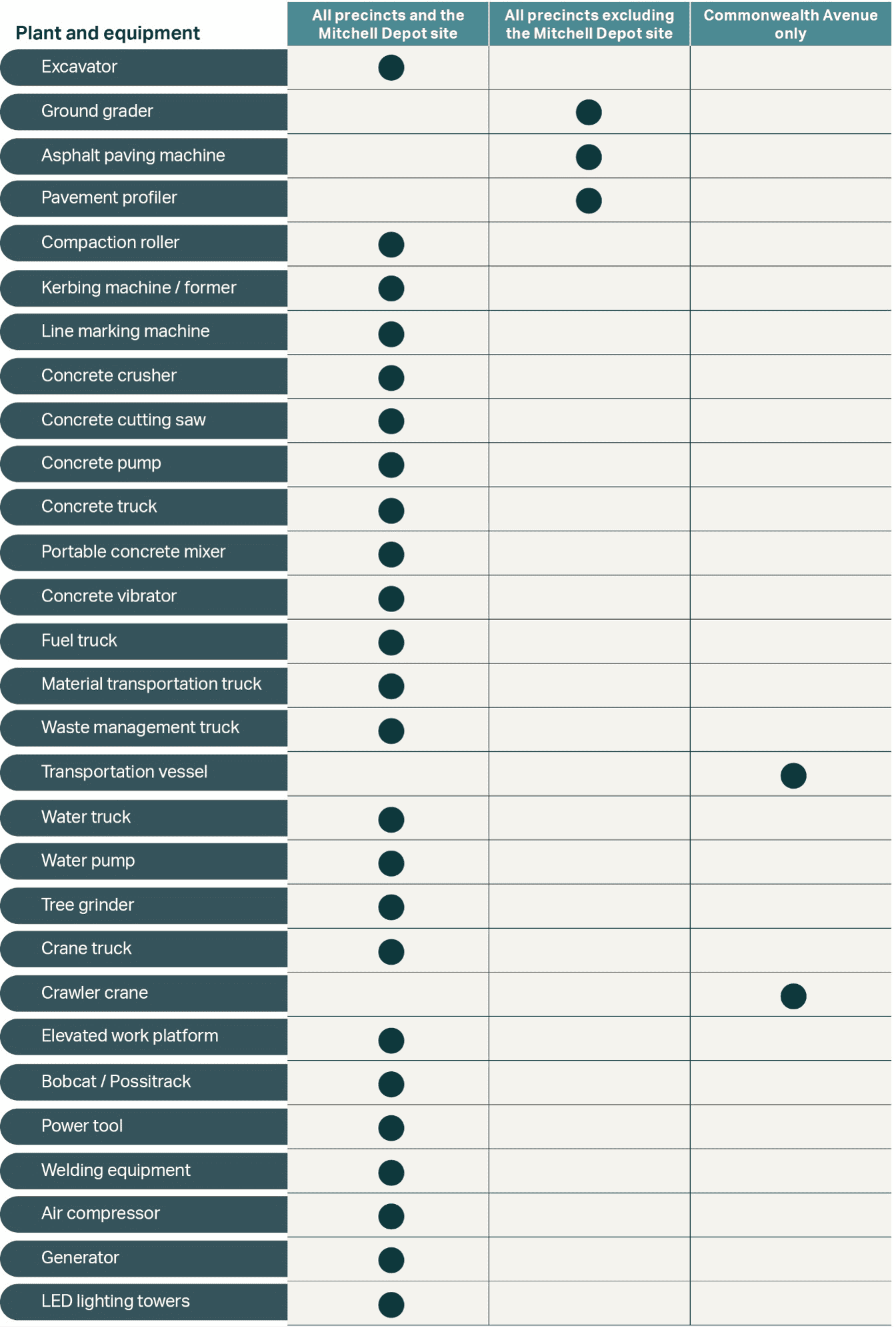
Plant and equipment used during construction would include machinery such as cranes, piling rigs, ballast tampers, excavators, milling/paving machines, semitrailers/dump trucks, compactors, vacuum excavation trucks, and road sweepers. On a smaller scale, construction would require generators, welding equipment, concrete saws, elevated working platforms, bobcats, line marking machines, jackhammers, and personal tools.
Figure 6-12 provides an indicative list of plant and equipment expected to be required during construction. Some plant and equipment that has been identified for the Commonwealth Avenue precinct only is specific to construction activities over Lake Burley Griffin.
6.6.4 Construction materials
Raw materials
Materials required during construction would include raw materials such as aggregates and asphalt, concrete, metals (such as steel rails, structural steel, steel reinforcement, over-head wiring, prefabricated steel furniture and signage), diesel, and oils. Other materials required would be confirmed during design development and construction planning.
Further details of the materials expected to be used, including an indicative estimate of required quantities, is provided in Section 11.12.
Water use
The use of water during construction would be required for activities such as:
- Dust suppression
- Road pavement works, including compaction of pavement
- Site office and amenities
- Concrete construction
- Cutting equipment, such as concrete cutters
- Landscaping.
It is expected that the construction of the Project would involve connection to potable water supply sources (subject to agreement with the relevant authority), with the potential to deliver water to the Project area from a licensed source, if required.
Further information on materials and resources to be used are provided in Section 11.12.
6.7 Transport and access
This section provides an overview of the intended transport and access arrangements during the construction phase. The potential impacts of construction on transport, traffic, and access are described in the Traffic and transport sections in Part B (Environmental impact assessment), and the management and mitigation measures that would be implemented to manage these impacts are described in Chapter 21(Environmental management and mitigation measures).
6.7.1 Heavy vehicle routes
Anticipated heavy vehicle haulage routes during construction are shown in Figure 6-13 to Figure 6-18. Heavy vehicle movements would be generally for deliveries of construction plant and equipment, supplies and infrastructure, and to transport spoil and waste materials.
The scheduling of construction heavy vehicle movements, including the transportation of oversized loads, would occur outside peak AM and PM traffic periods whenever feasible.
6.7.2 Construction traffic volumes
Estimated construction traffic volumes are summarised in Table 6-5 and Table 6-6 for day shifts and night shifts, respectively.
| Heavy vehicle movements | Light vehicle movements (construction activities) | Light vehicle movements (workforce) | Total vehicle movements | |||||
|---|---|---|---|---|---|---|---|---|
|
Precinct/site |
Day shift1 |
Peak2 |
Day shift1 |
Peak2 |
Day shift1 |
Peak2 |
Day shift1 |
Peak2 |
|
Commonwealth Avenue |
25 |
5 |
30 |
5 |
235 |
0 |
290 |
9 |
|
Parliament House |
135 |
25 |
20 |
5 |
145 |
0 |
295 |
25 |
|
National Triangle |
25 |
5 |
20 |
5 |
170 |
0 |
215 |
10 |
|
Barton |
15 |
5 |
20 |
5 |
125 |
0 |
160 |
5 |
|
Inner South |
65 |
15 |
20 |
5 |
330 |
0 |
410 |
15 |
|
Yarra Glen |
70 |
15 |
20 |
5 |
130 |
0 |
215 |
15 |
|
Woden |
30 |
5 |
20 |
5 |
150 |
0 |
195 |
10 |
|
Mitchell Depot |
20 |
5 |
10 |
5 |
160 |
0 |
190 |
5 |
Notes:
1.Daily vehicle movements represent maximum inbound and outbound movements across the day shift for the peak construction period. Movement refers to a one-way movement. A vehicle entering and then leaving a construction compound represents two movements.
2.Peak vehicle movements represent the maximum number of vehicle movements during the morning and afternoon road network peak periods (8:00 am to 9:00 am and 5:00 pm to 6:00 pm) for the peak construction period.
| Heavy vehicle movements | Light vehicle movements (construction activities) | Light vehicle movements (workforce) | Total vehicle movements | |||||
|---|---|---|---|---|---|---|---|---|
|
Precinct/site |
Night shift1 |
Hourly2 |
Night shift1 |
Hourly2 |
Night shift1 |
Hourly2 |
Night shift1 |
Hourly2 |
|
Commonwealth Avenue |
15 |
5 |
15 |
5 |
105 |
30 |
130 |
30 |
|
Parliament House |
60 |
10 |
10 |
5 |
65 |
20 |
135 |
30 |
|
National Triangle |
15 |
5 |
10 |
5 |
80 |
20 |
95 |
25 |
|
Barton |
10 |
5 |
10 |
5 |
60 |
15 |
70 |
20 |
|
Inner South |
30 |
5 |
10 |
5 |
150 |
40 |
185 |
45 |
|
Yarra Glen |
35 |
5 |
10 |
5 |
60 |
15 |
100 |
25 |
|
Woden |
15 |
5 |
10 |
5 |
70 |
20 |
90 |
20 |
|
Mitchell Depot |
10 |
5 |
5 |
5 |
75 |
20 |
85 |
20 |
Notes:
1.Daily vehicle movements represent maximum inbound and outbound movements across the night shift for the peak construction period. Movement refers to a one-way movement. A vehicle entering and then leaving a construction compound represents two movements.
2.Represents the maximum number of vehicle movements per hour for the night peak periods (6:00 pm to 7:00 am) for the peak construction period.
6.7.3 Construction workforce parking
Construction workforce parking would involve:
- For most construction compounds and construction sites, parking requirements would be satisfied with a combination of parking spaces within construction compounds as well as public parking
- At construction compounds A1 and A2, workforce parking within the construction compounds would not be available and staff would instead utilise public parking
- At the Mitchell Depot site, most parking would be provided within the site where feasible.
Construction workers would be encouraged to use public transport to access the Project during construction. Consideration would be given to providing shuttle services to transport construction workers. If shuttle services are not provided as part of the Project, parking restrictions around work areas would be considered to reduce the impact on public parking facilities.
6.7.4 Temporary changes to transport networks and facilities
Transport network
The construction of the Project would apply traffic management measures to maintain the operational capacity of nearby roads and ensure the safety of the public, motorists, and construction workers. Some modifications to the road network would be necessary during construction, such as:
- Installation of temporary traffic signals to allow for the safe movement of construction traffic
- Temporary road, access, or lane closures (for example, closure of one lane in each direction on the existing Commonwealth Avenue road bridges to support construction of a new light rail bridge over Lake Burley Griffin)
- Temporary intersection adjustments or closures.
For the State Circle East alignment option, one lane in each direction of travel would remain open to traffic during construction. For the National Triangle-Barton alignment option, progressive road closures along sections of the alignment would be required due to road width restrictions within the National Triangle and Barton precincts. Local traffic access would be maintained.
Temporary road closures would be limited to the duration of works requiring the closure. Alternative access arrangements and detour routes would be provided, including to private properties and businesses. Further information in relation to construction traffic and transport is provided in Technical Report 1 - Traffic and transport.
Parking
In certain areas, on-street and off-street parking may be removed to allow enough space for construction activities, to ensure ongoing access along the road network, and to facilitate use of construction compounds (refer to Section 6.6.1). The temporary loss of parking could vary in duration, lasting from less than a day to more extended periods (e.g. up to the construction phase duration), depending on the necessary works in individual areas.
Potential temporary and permanent on-street and off-street parking impacts are detailed further in Technical Report 1 - Traffic and transport.
Public transport
Bus stop relocations would not be required for the State Circle East alignment option as no full road closures would be required.
For the National Triangle-Barton alignment option, several bus stops would require relocation due to full road closures during construction. Bus services would need to be rerouted through the National Triangle and Barton precincts, including routes R2, R6, 56, 59, and 182.
Affected services would be diverted and bus stops would be relocated along their existing routes during construction, where practical. Rerouting of bus services would be required where bus stops are not able to be relocated along the existing routes. The details of any changes to bus stops and/ or routes would be determined in consultation with relevant stakeholders, including Transport Canberra City Services (TCCS).
There would also be temporary impacts to the Commonwealth Park Stop when connecting the Project to the stop. Works would be scheduled to minimise disruption to light rail services.
Further information on potential impacts to public transport is provided in Section 11.1.
Pedestrian and cyclist facilities
Modifications to the road network and access limitations in work zones would affect pedestrian walkways and cycling paths. Alternative access arrangements (such as detours) would be provided.
All pedestrian and cycle facility adjustments would be consistent with AS 1428 DDA and Disability Standards Accessible Public Transport.
6.7.5 Changes to maritime infrastructure and navigation
Construction works associated with the light rail bridge between the Commonwealth Avenue road bridges over Lake Burley Griffin would require access to boat ramps and jetties. The public thoroughfare/ open navigation channel beneath the bridges would also be affected (moved locations for public access under the bridge depending on where construction barges are positioned) however access would be maintained throughout the construction period. These activities would likely result in temporary restrictions to public access in these areas for safety reasons, with access maintained as far as practicable.
These restrictions would be temporary, and access reinstated once the relevant construction activities are completed.
6.7.6 Special events
Known special events that would fall within the construction schedule (for example Floriade and Skyfire) would be managed and suitable measures implemented to manage and mitigate the anticipated impacts of construction. This may include temporary pauses in construction, traffic management and contingency plans. The traffic management necessities for special events may involve modifications to the construction schedule and routes utilised by heavy vehicles.